RUD sling and lashing systems
- การเชื่อมต่อบาลานเซอร์ด้านบน: เชื่อมต่อด้วยสะดึงยก (Shackles)
- การเชื่อมต่อบาลานเซอร์ด้านล่าง: เชื่อมต่อด้วยข้อต่อรุ่น ICE-Connection links
- สังเกตและตรวจสอบมุมเอียงจำกัดที่ 10 องศาได้อย่างง่ายดาย ด้วยรูปทรงการออกแบบพิเศษที่บริเวณฐานของบาลานเซอร์
- สามารถดูข้อมูลรายละเอียดเพิ่มเติมของบาลานเซอร์รุ่น ICE-Balancer ได้ในคู่มือการใช้งาน
- ข้อควรทราบและปฏิบัติตามเมื่อใช้งานชุดแขวน ICE-BALANCER:
- น้ำหนักของชิ้นงานยกต้องมีความสมมาตร (Symmetrical)
- มุมเอียง β ต้องไม่เกิน 45 องศา (ดูไดอะแกรมที่ 1 และ 2)
- มุมเอียงของตัวบาลานเซอร์ต้องไม่เกิน 10 องศา (ดูไดอะแกรมที่ 3, 4 และ 5)
- สามารถดูข้อมูลรายละเอียดเพิ่มเติมของบาลานเซอร์รุ่น ICE-Balancer ได้ในคู่มือการใช้งาน
- พิกัดการรับน้ำหนัก (WLL) ที่สูงขึ้น ณ มุม β = 15 องศา หรือ β = 30 องศา สามารถดูเพิ่มเติมได้ในคู่มือการใช้งาน
- สำหรับชุดยกแบบ 4 สาย (4-strand) โดยทั่วไปจะคำนวณพิกัดการรับน้ำหนักจากสายโซ่สูงสุดเพียง 3 สายเท่านั้น และในกรณีที่ทิศทางการยกไม่เอื้ออำนวย (Unfavourable cases) อาจมีสายโซ่ที่รับน้ำหนักจริงเพียง 2 สาย
- คำแนะนำของเรา (TIP):
- เมื่อใช้งานชุดยกแบบ 2 x 2 สาย (2 x 2-strand) ตามรูปแบบโครงสร้างที่แสดง จะช่วยให้กระจายน้ำหนักไปยังโซ่ทั้ง 4 สายได้อย่างทั่วถึงเท่ากัน และให้พิกัดการรับน้ำหนัก (WLL) สูงขึ้นถึง 33% เมื่อเทียบกับชุดยก 4 สายมาตรฐานทั่วไป
- โครงสร้างส่วนหัวของ ICE-BALANCER รุ่น IWK-2S ประกอบด้วย:
- ห่วงมาสเตอร์ลิงก์รุ่น IA link พร้อมข้อต่อ IKZA
- สะดึงยกรุ่น VIP-Shackles
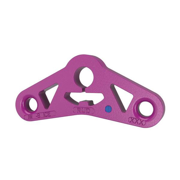
- ตัวบาลานเซอร์ ICE-Balancer
- ข้อต่อรุ่น ICE-Connecting links จำนวน 2 ชิ้น
- Balancer connection at top: Connection by shackles.
- Balancer connection at bottom: ICE-Connection links.
- Easy recognition of the limit tilt angle of 10° due to special shaping on the bottom of the balancer.
- Detailed information on the ICE-Balancer can be found in the operating manual.
- PLEASE NOTE THE FOLLOWING WHEN USING THE ICE-BALANCER SUSPENSION:
- The load must be symmetrical.
- The inclination angle β must not be greater than 45° (see diagrams 1 and 2).
- The inclination of the balancer must not be greater than 10° (see diagrams 3, 4 and 5).
- Detailed information on the ICE-Balancer can be found in the operating manual.
- Higher WLL at β = 15° or β = 30° see operating manual.
- With a 4-strand suspension, a maximum of only 3 strands can be assumed to be load-bearing. In unfavourable cases only 2 strands are used.
- Our TIP:
- When using a 2 x 2-strand suspension in the configuration shown, an even load distribution to all 4 strands and a 33 % higher WLL than a standard 4-strand suspension.
- DESIGN OF ICE-BALANCER HEAD IWK-2S CONSISTING OF:
- IA link with IKZA.
- VIP-Shackles.
- ICE-Balancer.
- 2 ICE-Connecting links.
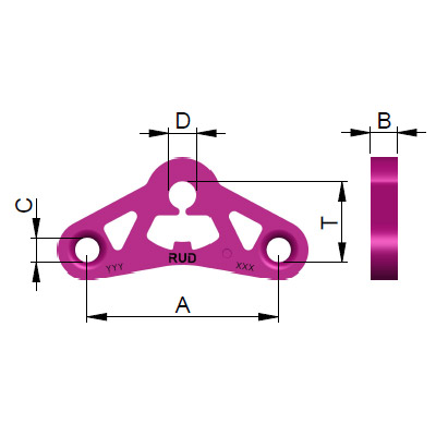
Article number: 7904367
| Attribute | Value | Value |
|---|---|---|
| Attributeweight | Value0.49 kg | Value1.08 lbs |
| AttributeT | Value46 mm | Value1-13/16" |
| AttributeA | Value110 mm | Value4-11/32" |
| AttributeB | Value15 mm | Value19/32" |
| AttributeC | Value14 mm | Value9/16" |
| AttributeD | Value21 mm | Value13/16" |
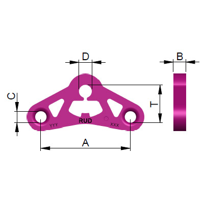
Article number: 7904370
| Attribute | Value | Value |
|---|---|---|
| Attributeweight | Value1.16 kg | Value2.56 lbs |
| AttributeT | Value59 mm | Value2-15/16" |
| AttributeA | Value150 mm | Value5-7/8" |
| AttributeB | Value20 mm | Value3/4" |
| AttributeC | Value18 mm | Value23/32" |
| AttributeD | Value26 mm | Value7/8" |
Article number: 7904372
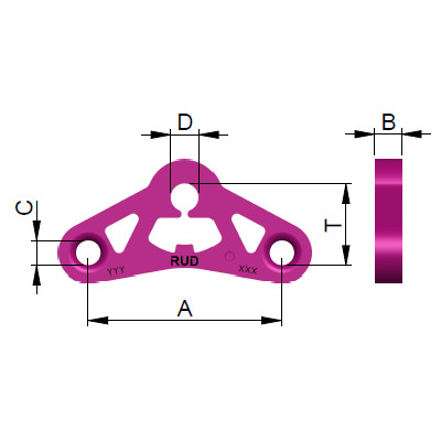
| Attribute | Value | Value |
|---|---|---|
| Attributeweight | Value2.20 kg | Value4.85 lbs |
| AttributeT | Value76 mm | Value3" |
| AttributeA | Value180 mm | Value7-1/16" |
| AttributeB | Value25 mm | Value63/64" |
| AttributeC | Value23 mm | Value29/32" |
| AttributeD | Value32 mm | Value1" |
Article number: 7904375
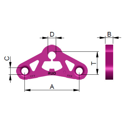
| Attribute | Value | Value |
|---|---|---|
| Attributeweight | Value4.37 kg | Value9.63 lbs |
| AttributeT | Value91 mm | Value3-9/16" |
| AttributeA | Value240 mm | Value9-1/2" |
| AttributeB | Value30 mm | Value1-3/16" |
| AttributeC | Value28 mm | Value1-1/8" |
| AttributeD | Value38 mm | Value1-1/2" |
Article number: 7904255
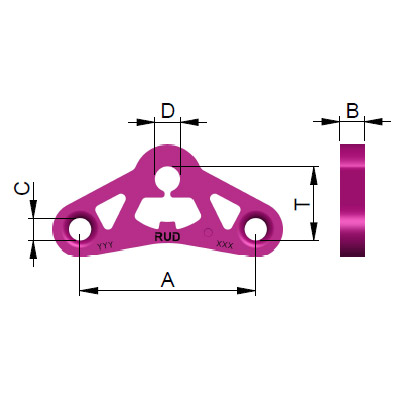
| Attribute | Value | Value |
|---|---|---|
| Attributeweight | Value8.80 kg | Value19.40 lbs |
| AttributeT | Value120 mm | Value4-3/4" |
| AttributeA | Value300 mm | Value11-13/16" |
| AttributeB | Value35 mm | Value1-3/8" |
| AttributeC | Value32 mm | Value1-1/4" |
| AttributeD | Value41 mm | Value1-5/8" |